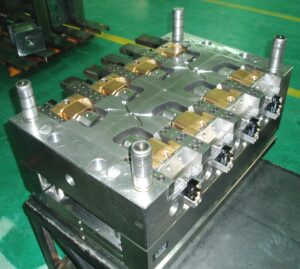
Plane Vents

The principal kind of vent to be considered is the vent on the splitting plane. These vents are regularly given as exceptionally slight channels legitimately toward the finish of stream. Numerous molds are created with vents on the splitting plane that radiate from the edge of the splitting line outwards to a thicker vent”relief” or vent”channel.” Figure 8.6 gives a venting framework plan to the bezel, in which two vents have been given within and outside surfaces of the pit embed. The width of the vent, W, has been made deliberately high to accommodate vulnerability in the last territory of the liquefy to fill the pit. The thickness of the vent, hvent, has been determined as 0.05 mm, The length of the vent, L, is 2 mm, after which the wind currents through a 2 mm thick channel to a 3 mm distance across outlet situated at the middle and head of the addition.

While vents ought to be given on the splitting plane toward the finish of fill, it isn’t unprecedented for vents to be set intermittently around the outskirts of the cavity. For the trim of focus gated barrel shaped parts, vents can be set around the fringe of the whole form depression in high-precision mould china. In this plan, the pit for a top is focus gated as in a three-plate or hot sprinter form. A vent is put around the whole fringe of the shape depression. Given the adequate vent width, the vent is determined with a thickness of 0.015 mm and a length of 1 mm. A vent channel interfaces the vent ring to the side of the supplement and ensuing outlets.

While the above plans are absolutely viable regarding venting the uprooted air, it ought to be referenced that they are vulnerable to glimmering with twisting of the shape plates. As will later be examined in the auxiliary plan of Chapter 12, the dissolve pressure applies huge powers on the form pit and center. Any huge diversion will in general expand the thickness of the vents and in this way improve the probability and measure of glimmering. In reality, the plan of Fig. 8.7 might be particularly dangerous since the outside, base surface of the top is a region watched and dealt with by the end client. The utilization of an inward vent around the outskirts of a stripper plate will settle this issue as later planned in china mould manufacturing manufacturers.

To maintain a strategic distance from unreasonable glimmering and related support, it is suggested that vents on the splitting plane be utilized sparingly with a thickness on the request for 0.02 mm. On the off chance that venting is hence discovered to be lacking, at that point extra vents can be included or the thickness of existing vents expanded.
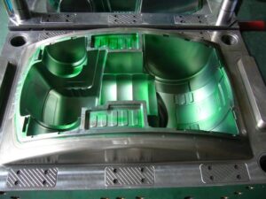
An exceptionally normal practice is to utilize the leeway around ejector pins for venting purposes. There are numerous preferences to this vent plan. To begin with, the incitation of the ejector serves to at any rate mostly clear the venting channel between the pin and the center. Second, ejector pins are normally utilized and surely known. Since a leeway should be indicated around the pin to give a sliding fit in any case, it is practical to determine a freedom appropriate for venting.

This article is from http://www.chinainjectionmold.com/
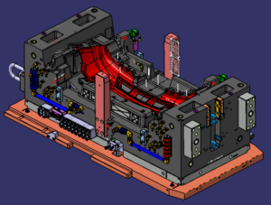
Vent Dimension

When the quantity of vents is indicated, the pace of wind stream through each vent can be determined by china high-precision mould suppliers. It might appear to be sensible to gauge the wind current through each vent as the absolute volumetric wind stream partitioned by the quantity of vents. Nonetheless, this methodology would not be moderate. The explanation is that the specific area of the finish of fill isn’t known. All things considered, it is conceivable that a great part of the wind stream can excessively support any of the four areas on each side of the part. A more traditionalist methodology is to expect that all the neighborhood wind current ways out through each accessible vent.

When all is said in done, the length and width of the vent are controlled by the application math. The base vent thickness is identified with the compel drop over the vent important to deliver the uprooted air. The base thickness can be determined utilizing examination of the air as a laminar, gooey stream as indicated by the Newtonian model recently introduced. While air moving through vents might be better displayed as a compressible, violent stream, the accompanying investigation is easier while additionally incredibly moderate. The weight drop of a Newtonian liquid in a rectangular channel.

It is again accentuated that the past investigation and model are moderate since the investigation expected laminar stream for the air thus proposes higher weight drops and the requirement for thicker vents than a tempestuous stream, the calculation and cycle conditions apply to a solitary, little vent with moderately high wind current, and the accepted thickness of air at room temperature is higher than would happen if the air were warmed by the polymer soften or pressure. Consequently, the base thickness of the vent won’t by and large be a restricting plan limitation.

The greatest size of the vent is identified with the most extreme measure of blazing that is average at the vent areas. The development of blazing in incredibly dainty channels, for example, vents is a serious examination point, requiring transient reproduction coupling the warmth move and liquid stream just as a profoundly refined work with extremely little league steps. No basic explanatory arrangement exists. Notwithstanding, with the end goal of conversation just, think about the use of laminar gooey stream. The normal volumetric stream pace of the liquefy during the blazing.

Since the above investigation might be hard to apply given the imperative presumptions, a few suggestions for vent thickness are recorded by china industrial injection mold manufacturers from different handbooks. The distinctions in the proposals are fascinating and reasonable to a limited extent. Most of the fluctuation probably originates from the way that there has been a drawn out pattern in the plastics business to move to more slender dividers, quicker injection rates, and higher injection pressures; the greatest thickness of the vent diminishes with expanding melt pressure. Simultaneously, material producers have tried to diminish the consistency of plastic tars while improving auxiliary properties. Appropriately, it ought not be astonishing that the specialized guidelines for vents change, with more slender vents being as of late suggested.

This article is from http://www.chinainjectionmold.com

Venting

Venting is regularly a minor part of mould plan for any china industrial injection mold manufacturers, and habitually dismissed until trim preliminaries demonstrate shape deficiencies identified with venting. A comprehension of the reason and capacity of vents can help the form planner to configuration vents where unmistakably required and guarantee that the shape may oblige extra vents when required.

The essential capacity of the vent is to deliver the air in the shape that is being dislodged by the profoundly pressurized plastic dissolve. In the event that all the air in the depression isn’t taken out during the filling stage, at that point a few imperfections can result. To begin with, the caught air can shape an exceptionally pressurized pocket in the form depression through which the soften can’t stream, framing a short shot in the formed item. Second, the profoundly compacted, high temperature gas can combust within the sight of the plastic liquefy, causing a marvel known as”dieseling”and an imperfection known as”burn marks.” If the consume marks show up on a tasteful surface, the disintegrate should dismiss the shaped part. Third, the presence of gas between two merging melt fronts can diminish the part quality because of impedance of the air with the two welding liquefies while likewise shaping v-indents on the outside of the formed part that go about as a pressure focus during the part’s end use.

Since an absence of venting is related with a few noteworthy imperfections, numerous wide and thick vents are attractive at various areas to encourage the wind stream out of the hole. In any case, on the off chance that a vent is excessively thick, at that point the polymer soften can leak out of the vent, causing a slim however sharp line of plastic blaze to shape at the vent areas. In many embellishment applications, this glimmer should be managed by the machine administrator utilizing a deburring instrument. Such deflashing is bothersome since the administrator causes work cost at this point doesn’t give 100% consistency. Moreover, on the off chance that a disintegrate proceeds with activity with unreasonable blazing, at that point the form’s splitting plane can wear and require reemerging. Thus, less and littler vents are liked.

The utilization of vents additionally by injection mould tooling china gives more highlights on the shape that can require support. Numerous polymers will off gas in the liquid state, delivering particles that can develop and obstruct the venting framework. Such stopped up vents can happen particularly rapidly with the utilization of form discharge. Subsequently, the trim cycle may discontinuously create deserts identified with an absence of venting. Many decays settle this issue by fusing vent cleaning as a component of a preventive support program. Regardless, the shape fashioner ought to endeavor to configuration venting frameworks that require insignificant support, and are anything but difficult to keep up when required.

A three stage investigation measure is suggested to injection moulding services for the examination and plan of vents. To begin with, the air relocation rate should be assessed comparative with the liquefy stream rate. Second, the number, type, and area of vents must be evaluated. Third, the width, length, and thickness of each vent must be determined. Regarding the thickness choice, the thickness must be more noteworthy than some base an incentive to guarantee sufficient venting while additionally littler than some most extreme add up to maintain a strategic distance from inordinate glimmering.

This article is from http://www.chinainjectionmold.com/

Pressure Drop and Gate Freeze

In the event that in oem/odm industrial injection moulding design factory the shear rates are inside as far as possible, at that point the weight drops are likely satisfactory too, However, the weight drop through the entryway ought to be determined to guarantee that sufficient infusion pressure is accessible to fill the shape pit; door measurements can likewise be acclimated to change the area of weld-lines in the form cavity. The weight drops are determined by the recently given conditions to gooey stream in strips and chambers. For reference, the formulae for Newtonian and force law streams are given.

In assessing the weight drop through doors, it is essential to figure the consistency at the fitting shear rate when utilizing the Newtonian model, or on the other hand utilize the conditions for the force law model. The weight drop through the doors may shift from right around zero to a few MPa. Weight drops over 10 MPa are normally characteristic of inappropriately planned entryways that are either excessively slight or excessively long.

After the shape depression is loaded up with the polymer soften, extra material must be constrained into the hole to make up for volumetric shrinkage as the dissolve cools. As the liquefy in the hole cools, the soften in the entryway will likewise will in general cool. The solidified skin will engender from the form divider to the centerline of the entryway. Since no extra soften stream can be provided to the cavity once the door freezes, the disintegrate should set up the embellishment machine to end the pressing stage at entryway freeze off and start the plastication stage. The door freeze time must be adequate to take into account pressing of the polymer in the form depression.

The cooling of the liquefy in the cavity and the utilization of the related warmth condition will be talked about in pom moulding parts manufacturers china. Utilizing the gave investigation, the mass liquefy temperature is plotted as a component of time for a 2 mm measurement barrel shaped entryway for ABS at midrange dissolve and coolant temperatures. The mass temperature of the polymer in the door will at first be near the set dissolve temperature of 240°C,and at that point decline in the post-filling stage as the warmth moves to the colder shape dividers. It would in the end arrive at the shape coolant temperature of 80°C.

Injection molding service china utilizing the Cross WLF consistency model, the evident thickness of the polymer dissolve in the door at a shear pace of 10 1/s is likewise plotted in Fig. 7.18. It is seen that the consistency of the plastic liquefy is at first low, and afterward starts to increment exponentially as the temperature diminishes. In the end, the consistency will increment with the end goal that no stream is successfully communicated through the entryway and the pressing stage should end, For this situation, a thickness of 100,000 Pa s has been subjectively chosen as a”no-stream” condition, relating to a door freeze season of about 1.5 s. Supplement A gives the “no-stream temperature”for different materials assessed as such.

For reference, the conditions to ascertain the door freeze time are accommodated rectilinear and strip calculations. These conditions will give the base pack times since they expect flawless warmth conduction between the soften and the shape divider. Practically speaking, entryway freeze times will be longer since these conditions don’t consider the soften course through the door into the hole and the related convection of warmth that will in general forestall the freezing of the entryway. Hence, the length of the pressing stage ought to be relied upon to be fairly longer than those anticipated with the conditions. All things being equal, the conditions are helpful to give a gauge of the significant degree of the polymer cementing time in the entryway.

This article is from http://www.chinainjectionmold.com.

Valve Gate

Hot runner providers of injection moulding services china have attempted to determine these issues, however with restricted achievement. For trim applications including continuous shading changes or the utilization of shear touchy or intensely filled materials, it is alluring to smooth out the move through the door and lessen the shear rates. As needs be, the warm sprue door configuration has been created. In this plan from mould manufacturers factory, a spout tip is used that has a long contact length with the encompassing mold. This permits the entryway territory at the cavity to cool essentially, with the end goal that no protecting layer of plastic is required. An open stream bore inside the spout and spout tip would then be able to control the plastic liquefy legitimately to the pit. After the dissolve fills the form, the whole sprue beneath the warm entryway soldifies. A lot of combining veering tightens in the spout tip directs the break purpose of the sprue, leaving a slim layer of set plastic behind to seal the plastic dissolve.

Contrasted with the warm pin-point entryway, the warm sprue door furnishes an open stream held on for decreased shear rates and weight drop. Since the shear rates are decreased, the warm sprue entryway is more qualified for use with shear delicate and vigorously filled materials. Because of its open stream bore, besides, the warm sprue door normally requires less embellishment cycles when hues 0r materials are changed.

One less obvious yet significant preferred position is that the length of the sprue can be intended to permit freedom for ribs or other cavity subtleties that exude towards the feed framework and may forestall direct gating with a warm pin-point door. There is one noteworthy weakness of the warm sprue door, in any case. Since a sprue is moldd with the part, it must stay with the part as remnant or in any case be later disengaged by the administrator or another post-forming measure.

Warm doors are efficient and by and large reasonable for a wide scope of trim applications and materials. Be that as it may, both the pin-point and sprue warm doors have two expected restrictions. To begin with, they depend on a set layer of plastic to forestall spillage, and this set layer may not be adequate in an assortment of conditions. Second, warm doors give a huge entryway remnant that may not be worthy in numerous applications. To determine the impediments of the warm door, precisely impelled valve entryways have been created. During activity, the valve pin is withdrawn to give admittance to the mold cavity. After the pit is filled and pressed, the valve pin is progressed to seal the door.

Valves entryways have in any event three critical points of interest over warm doors. To start with, valve entryways give a mechanical seal (steel on steel) as are more powerful regarding forestalling melt spillage. Second, the essence of the valve pin presents a mold shut-off surface to the form cavity when shut and along these lines altogether lessens the door remnant. Third, opening and shutting of valve pins might be planned to successively fill multigated mold in order to dispose of weave lines or deliberately control pressing weights to improve part quality.

Lamentably, valve entryways increment the expense and multifaceted nature of the mold, The costis expanded because of the expansion of the valve pins, actuators, and a lot bigger top clip plate to house the actuators, hoses, fittings, and the control framework. In that capacity, the expense of a hot runner framework with valve doors might be double the expense of a hot runner system with warm entryways. Intricacy in activity of china high-precision mould suppliers is additionally expanded, as the administrator should effectively interface the hoses and determine timings to agree with the cycle settings on the embellishment machine.

This article is from http://www.chinainjectionmold.com

Mold Design Issues

For hot runner mold plans of high precision mould manufactory, the form planner should check the home season of the polymer liquefy in the hot runner to guarantee that the plastic won’t corrupt. The habitation time is straightforwardly identified with the quantity of goes needed to turn over the polymer soften in the hot runner system.

In the event that the volume of the hot runner is huge contrasted with the volume of the form holes, at that point many trim cycles might be needed to drive new material through the feed system. The quantity of turns doesn’t speak to the genuine number of embellishment cycles needed to cleanse the hot runner of the old gum, but instead the base number of trim cycles before a generous measure of the new gum is conveyed to the form holes.

A high number of turns is unfortunate for embellishment applications in which the shade of the pitch is oftentimes changed. To encourage continuous shading changes, mold creators ought to streamline the feed system measurements and downplay the quantity of turns. In the event that the quantity of turns is not exactly or near one, at that point the utilization of the hot runner system is probably not going to obstruct shading changes comparative with the shading change issues related with cleansing the injection unit of the embellishment machine from china molds produce services suppliers.

In the event that the quantity of turns is huge, on the request for at least 10, at that point cleansing the hot runner may turn into an extremely noteworthy issue with hundreds (or thousands) of embellishment cycles needed to totally cleanse low-consistency pitches. A high number of turns is additionally bothersome for trim applications with gums that have short permissible home occasions. The living arrangement season of material in the hot runner system is roughly.

This living arrangement time is estimated, since material moves through the hot runner system at different rates; the polymer liquefy close to the dividers and in dead spots of the hot runner can have any longer habitation times than those anticipated by high precision plastic injection mould manufacturers.

Moreover, the mold fashioner ought to recollect that the material streaming into the hot runner system has just lived in the barrel of the embellishment machine for a lot of time. In like manner, the form fashioner ought to endeavor to limit the quantity of goes to decrease the habitation time and possible corruption of the polymer dissolve.

One model, Compute the quantity of turns and habitation season of the hot runner planned. The hot runner configuration coming about because of a permitted 50 MPa pressure drop had a volume of 2 1.3 CC. Since the volume of the bezel pit is 27.5 CC, the quantity of turns is N turns=21.3 cc/27.5 CC-= 0.77

which is exceptionally low. New material will course through the hot runner system and into the form cavity with each cycle. China mould produce services factory, the process duration was assessed as 13.5 s. The home time in the hot runner system is assessed as

Tresidence=(1 + 0.77 cycles).13.5(S/cycle)= 24 S

This home time is exceptionally low contrasted with the permissible home season of most polymers, which is commonly on the request for 15 min [10], however numerous bioplastics may have significantly less warm security.

While oem/odm industrial mold design factory so far has examined the reason, types, and investigations of feed systems, there are some handy issues that the form originator ought to consider before finishing the feed system plan.

The gave examination applies to”full round”circular runners, since these are very regular in form plans and accommodate basic investigation. In any case, other runner cross segments are additionally genuinely basic practically speaking, since they are simpler to machine. Specifically, the trapezoidal, round base trapezoid, and half round runners are regularly machined into just the moving side of the mold.

This article is from http://www.chinainjectionmold.com

Runner Size

The past examination and molds applied to a normally adjusted stretching feed system. Be that as it may, the investigation can likewise be applied to”artificially adjusted” feed system plans for family forms and multi-gated parts. In these applications of high precision plastic injection mould suppliers, distinctive stream rates and weight drops might be wanted for each part of the feed system.

To appropriately adjust the stream rates and soften pressures in a shape with complex Cavity calculations, it is important to guarantee that the polymer dissolve finishes the filling of each part of the form at around a similar time. Accordingly, the initial step of the examination is to ascertain the ideal volumetric stream rate to every hole, or for a multi-gated part, in each bit of the pit. The filling pressure at each entryway is . At that point assessed expecting this stream rate. When the hole pressures are known, at that point the weight drops through each bit of the runner system of high precision molds made in china can be planned with the recently portrayed investigation to yield the ideal depression weight and stream rate.
While this examination approach is as basic as could reasonably be expected, it doesn’t represent disparities in the occupying season of the feed system itself. This mistake is regularly unimportant since the feed system has a little volume contrasted with the shape depressions for cold runner forms and is as of now filled for hot sprinter molds. All things being equal, the absolute occupying time and weight of each part of the feed system and the shape cavities ought to be assessed to guarantee a really adjusted plan; numerous emphases might be expected to accomplish an adequate plan.

The mold designer of china cnc machine for mold making ought to perceive that a really ideal, adjusted form configuration is incredibly hard to accomplish. Since polymer dissolves are non Newtonian and the shear rates shift with sprinter breadth and stream rates, the im balance over the feed system is an element of the material properties and the preparing conditions.

Besides, there is no assurance that a feed system intended to adjust the stream rates during the filling stage will likewise adjust the pac ruler pressures during the posi-illing stage. Thusly, the shape planner ought to endeavor to lessen the measure of adjusting required by the feed system by guaranteeing the consistency of the form hole plans with the understanding that there will be cutoff points to the presentation of static feed systems.

For cold runner form plans, the shape planner should appraise the time needed to set the cool sprinter just as the time needed to harden the depression. The cementing times can be assessed through one – dimensional warmth move investigation as examined by china industrial injection mold suppliers. Table 6.2 gives the cooling time conditions to strips and chamber calculations, where h is the divider thickness of the pit, D is the breadth of a part of the feed system, Teiect is the predefined launch temperature (generally taken as the redirection temperature under burden, or DTUL), Tcoo Oolant is the coolant temperature, and Tmelt is the soften temperature.

During the embellishment cycle, the cooling time will be overwhelmed by whatever segment of the shape requires the longest an ideal opportunity to cool. Consequently, it isn’t important to compute the cooling times for each bit of the feed system and each shape pit thickness. Rather, the form planner can essentially check the cooling time for the thickest shape pit area and the biggest feed system measurement (for the most part the distance across at the base of the sprue). In the event that the cooling season of the feed system enormously surpasses the cooling season of the shape pits, at that point the form architect ought to overhaul the feed system to abstain from expanding the trim process duration.

This article is from http://www.chinainjectionmold.com/.

Feed System Design

Mold designers from high precision plastic injection mould factory are allowed to build up the feed system design to best accommodate their embellishment application. As recently examined, the essential inspiration is to give adjusted stream and insignificant weight drops while expending minimal measure of material. Accordingly, many feed systems use a cross breed of expanded and outspread designs. One such plan is appeared, which comprises of a fanned feed system with essential and auxiliary sprinters, which at that point takes care of four separate outspread feed systems, each with four tertiary sprinters. Contrasted with the feed system formats, the mixture format of the feed system configuration uses less material while additionally giving normally adjusted stream.

Many embellishment application necessities are best satisfied by custom feed systems that don’t consent to any of the past feed system formats. For instance, numerous multigated parts require the feed system to convey soften to various areas over the mold pit. In such embellishment applications, there is no motivation to hold fast to either extended or outspread or even normally adjusted designs. Without a doubt, the mold architect ought to intentionally pick a feed system format and determine measurements that convey the ideal measure of polymer dissolve at the ideal liquefy weights to various bits of the mold cavities.

One case of a custom mold is appeared in china tooling maker. This feed system comprises of four essential sprinters. The two longer essential sprinters feed the polymer dissolve by means of four auxiliary runners to a generally huge part encompassing the feed system. The two little essential runners closer to the sprue are utilized to take care of littler mold cavities that give discretionary parts to get together with the enormous trim. These optional runners might be fitted with pivoting closed offs that can be introduced in the form to change the network of the feed system, and subsequently produce various blends of moldings while the mold is in the trim machine.

The exhibition of the feed system is eventually controlled by the inventiveness and care of the mold creator from china high precision mold supplier as indicated by the prerequisites of the embellishment application. The form creator has critical opportunity in the plan of the feed system. Be that as it may, some broad rules are as per the following:

■The complete length of the feed system ought to be as short as conceivable to limit (a) material utilization and (b) pressure drop through the feed system;

■Naturally adjusted feed systems furnish more prominent pit to-cavity consistency regarding melt stream, dissolve pressure, and formed part quality than falsely adjusted plans;

■The absolute number of branches in a feed system ought to be limited to evade exorbitant sprinter volume and potential liquefy temperature awkward nature;

■To limit pressure drop for a given feed system volume, the widths of the feed system are commonly biggest with the sprue and consequently become smaller with the essential, optional, and different sprinters with diminishing stream rates;

■Economic investigation by mould manufacture factory is imperative to decide the right number of form pits, the design of the mold cavities, and the sort of feed system; and Hot sprinter and three plate molds ought to be viewed as when pits in a two-plate mold hinder the ideal format of the feed system.

This article is from http://www.chinainjectionmold.com/
Two-Plate Molds

The formats of the various kinds of feed systems from high-precision mould manufactory and their going with segments are examined in more noteworthy detail.

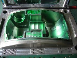
The two-plate mold is so named in light of the fact that it comprises of two amassed areas that sandwich the dissolve; every 50% of the form can comprise of at least one mold plates. A segment of an isometric mold is given in Fig. 6.4, in which the concealing speaks to the movement of the polymer liquefy. During the embellishment cycle, the spout of the trim machine mates with the span of the sprue bushing. The polymer dissolve first streams down the sprue bushing, accordingly crossing the thickness of the top brace plate and A plate. The material at that point streams over the splitting plane through sprinters and entryways into at least one mold pits.

After the polymer is completely infused and set, the mold is opened at the splitting plane, which is situated between the An and the B plates. Regularly, the A portion of the mold stays fixed while the B half of the form is pulled away with the moldings and sprinter framework staying on the center. To encourage launch, a converse mold is normally given on a take out pin beneath the sprue to guarantee that the sprue and appended sprinter stays with the B half. After the form has opened adequately to eliminate the moldings, the ejector plate is pushed forward by the embellishment machine. The sprue take out pin pushes on the sprue, breaking the little undercut and shooting the sprue from the B side of the mold. Extra ejector pins and take out pins can be put down the length of long sprinters to encourage launch of the feed framework.

In the plan of the feed system of oem/odm automotives injection molding factory, the length of the sprue is controlled by the joined thicknesses of the top clip plate and the A plate. The lengths of the sprinters are controlled by the situation of the depressions and the format of the related sprinters. Given this format, the mold creator needs to determine the widths of the feed framework. When all is said in done, the distances across of the upstream sprinters are bigger than the measurements of the downstream sprinters, since the progression of the polymer soften branches at sprinter intersections and there will be a lesser stream rate through every one of the downstream sprinters.

While a two-hole two-plate mold is utilized to show form plan ideas, the gave examination can be applied to more perplexing feed framework formats. For instance, china injection molded parts factory gives a feed system plan to an eight-cavity family form, including two essential sprinters, four optional sprinters, and eight tertiary sprinters. On the off chance that the stream rate through the sprue was 100 cc/s, at that point the stream rate through every one of the essential, optional, and tertiary sprinters would separately be 50 cc/s, 25 cc/s, and 12.5 cc/s. On the off chance that the stream obstruction in the depressions differed generously, nonetheless, at that point the stream rate in the tertiary sprinters could fluctuate considerably during the form filling stage.

Likewise with the feed system configuration appeared in oem/odm industrial mold factory, the distance across of each downstream sprinter is littler than the upstream sprinter appeared in Fig. 6.6. There is one prominent special case: the width of the trim machine’s spout opening is ordinarily littler than the distance across of the sprue delta. The littler opening in the machine spout gives a highlight division between the molded sprue and the cemented plug in the spout of the trim machine. In the event that the spout opening were bigger than the sprue bay, at that point a solidified part of plastic in the spout behind the sprue bushing could make the sprue adhere to the A portion of the mold. At the point when such staying occurs oftentimes, the decay may decide to perform a”sprue break” by withdrawing the infusion unit of the embellishment machine from the machine spout preceding mold opening and part launch. This activity is bothersome since it adds multifaceted nature and fluctuation to the embellishment cycle, so the form planner ought to check as well as suggest the spout hole measurement properly.

This article is from http://www.chinainjectionmold.com/

Feeding Amount for the Feed System

To accomplish the best feed system structure, the form fashioner ought to indicate the widths of the feed system to mutually limit the weight drop and the feed system volume. These plan imperatives are spoken by oem/odm largest plastic injection molding companies. As the breadths of the different fragments of the feed system increment, the weight drop diminishes underneath the predetermined greatest. Nonetheless, expanding the widths of the feed system additionally brings about an expansion in the volume of the feed system, which can be unwanted for both cold and hot sprinter feed systems.

In chilly sprinter structures, the enormous size of the feed system can bring about expanded process durations just as inordinate material waste related with the embellishment of the feed system. Some embellishment applications permit the utilization of regrind blended in with virgin material. An average breaking point on regrind might be 30%, which makes an interpretation of legitimately to a particular on the greatest volume of the feed system. For instance, in high precision plastic making mould china, on the off chance that a trim application had two pits adding up to 50 CC, at that point a 30% regrind detail would restrict the volume of the feed system to 15 CC.

In hot sprinter plans, huge feed systems lessen the turnover of the material in the hot sprinter. Low turnover is unfortunate for two reasons. Initially, long home occasions of the polymer liquefy in the hot sprinter can cause material corruption, which every now and again causes dark bits and diminished properties of the molded item.

Second, huge volumes of material in the hot sprinter system can hinder shading changes during trim, not just because of the huge volume of the plastic dissolve that should be flushed, yet in addition because of the low related shear worries in the polymer liquefy along the dividers of the feed system. Low shear worries during cleansing permit the material to adhere to the dividers of the hot sprinter, lessening the expulsion of old material during shading changes.

The most extreme volume of polymer dissolve in a hot sprinter feed system can be hard to determine since it is identified with the kind of material being formed, the need to perform shading changes, and the ideal weight drop. Hot sprinters are by and large progressively planned with littler breadths with the end goal that the material turns over each formed cycle. For instance, on the off chance that a trim application has two depressions adding up to 50 cC, at that point a turnover of the dissolve with each embellishment cycle would determine the volume of the feed system to be 50 CC. On the off chance that a low weight drop is wanted, at that point the volume of the feed system might be determined as 100 cc or even 200 cc if debasement and shading change issues are not anticipated. It ought to be noted, nonetheless, that not at all like a steel safe planned cold sprinter system, significant expenses might be caused to change the measurements of a hot sprinter system.

Since the essential capacity of the feed system is to pass on the dissolve from the trim machine to the shape depressions, it is attractive for the feed system to control the measure of polymer soften to each form pit. The two most normal applications relate to multicavity and multigated molds.

■In a multicavity mold in oem/odm medical injection mold factory, the trim application may require diverse weight drops in every leg of the feed system to make the distinctive form cavities occupy simultaneously. In this mold, in the event that the cup required a higher strain to fill than the cover, at that point the shape creator could give a lower pressure drop in the part of the feed system prompting the depression for the cup. Such a form configuration is known as”artificially adjusted.”

■In a multigated mold, a typical target in the feed system configuration is to control the polymer liquefy moving through the feed system to adjust the soften front progression in a multigated mold. For example, it might be attractive to drive more material through one door to move a sew line to an alternate area. Other basic uses incorporate the modifying of the form filling to wipe out a gas trap or abstain from overloading a segment of the shape pit.

Utilizing various measurements in the feed system can control the progression of the polymer liquefy, however there are restricts with regards to what can be accomplished. To begin with, the weight drop through every leg of the feed system is subject to the thickness of the polymer liquefy. Thusly, a falsely adjusted feed system may not adjust the form filling for various materials and handling conditions. Second, distinctively estimated feed systems will set at various rates and subsequently give various elements during the pressing phase of the embellishment cycle; sprinter sections with littler breadths will in general freeze rapidly and decrease the measure of pressing to downstream pits. Consequently, the form fashioner ought to endeavor to use shape pits that have comparative flling prerequisites. In the event that family forms or different needs direct totally different stream rates through each entryway, at that point the shape creator may wish to use dynamic dissolve control innovation.

This article is from http://www.chinainjectionmold.com.