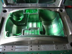
The principal kind of vent to be considered is the vent on the splitting plane. These vents are regularly given as exceptionally slight channels legitimately toward the finish of stream. Numerous molds are created with vents on the splitting plane that radiate from the edge of the splitting line outwards to a thicker vent”relief” or vent”channel.” Figure 8.6 gives a venting framework plan to the bezel, in which two vents have been given within and outside surfaces of the pit embed. The width of the vent, W, has been made deliberately high to accommodate vulnerability in the last territory of the liquefy to fill the pit. The thickness of the vent, hvent, has been determined as 0.05 mm, The length of the vent, L, is 2 mm, after which the wind currents through a 2 mm thick channel to a 3 mm distance across outlet situated at the middle and head of the addition.
While vents ought to be given on the splitting plane toward the finish of fill, it isn’t unprecedented for vents to be set intermittently around the outskirts of the cavity. For the trim of focus gated barrel shaped parts, vents can be set around the fringe of the whole form depression in high-precision mould china. In this plan, the pit for a top is focus gated as in a three-plate or hot sprinter form. A vent is put around the whole fringe of the shape depression. Given the adequate vent width, the vent is determined with a thickness of 0.015 mm and a length of 1 mm. A vent channel interfaces the vent ring to the side of the supplement and ensuing outlets.
While the above plans are absolutely viable regarding venting the uprooted air, it ought to be referenced that they are vulnerable to glimmering with twisting of the shape plates. As will later be examined in the auxiliary plan of Chapter 12, the dissolve pressure applies huge powers on the form pit and center. Any huge diversion will in general expand the thickness of the vents and in this way improve the probability and measure of glimmering. In reality, the plan of Fig. 8.7 might be particularly dangerous since the outside, base surface of the top is a region watched and dealt with by the end client. The utilization of an inward vent around the outskirts of a stripper plate will settle this issue as later planned in china mould manufacturing manufacturers.
To maintain a strategic distance from unreasonable glimmering and related support, it is suggested that vents on the splitting plane be utilized sparingly with a thickness on the request for 0.02 mm. On the off chance that venting is hence discovered to be lacking, at that point extra vents can be included or the thickness of existing vents expanded.

An exceptionally normal practice is to utilize the leeway around ejector pins for venting purposes. There are numerous preferences to this vent plan. To begin with, the incitation of the ejector serves to at any rate mostly clear the venting channel between the pin and the center. Second, ejector pins are normally utilized and surely known. Since a leeway should be indicated around the pin to give a sliding fit in any case, it is practical to determine a freedom appropriate for venting.
This article is from http://www.chinainjectionmold.com/