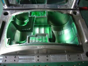
When the launch powers on the embellishment have been assessed, the following stage is to decide the total”push territory” of the ejectors onto the shaped part. In particular, there is a base push territory that is needed to maintain a strategic distance from inordinate compressive weight on the discharge system segments just as unnecessary shear weight on the plastic moldings. These two marvels are represented by china mould design services for a solitary pin shooting a bit of the PC bezel.
At the point when the pin is activated with the discharge framework, a response power, Fpin, will create between the pin and the shaped part before the part is shot out. The greatness of this power is identified with the all out discharge power needed to launch the part just as the number, area, and math of the ejectors. The compressive stres on the pin, Opin, is the power on the pin isolated by the region of the pin, or: σpin=Fpin/Aacompession
To stay away from exhaustion or potentially clasping of the launch framework segments, compressive feelings of anxiety must be kept up under a basic edge. This basic pressure, 0 fatigue_ limit is needy upon the material and treatment of the ejectors. Most ejector pins and sleeves are made of solidified materials, with exhaustion limit weights on the request for 800 MPa. A traditionalist shape plan, notwithstanding, may expect a lower weariness limit pressure of 450 MPa for P20. In one or the other case, the all out push territory, all things considered, Aejectors, to keep away from over the top compressive anxieties must meet the necessity.
The necessary push territory to evade abundance compressive anxieties in the discharge framework is exceptionally little in most trim applications invigorated the moderately high of steel. High-precision molds made in china know that the compressive quality of the pins is accordingly not compelling the plan.
Be that as it may, the ejector framework should likewise have enough push zone to try not to create exorbitant shear stresses in the shaped parts upon discharge. For oem/odm industrial injection moulding design factory, the shear pressure applied on the formed part is the power on the pin separated by the territory of the shaped part straightforwardly over the boundary of the pin, or: :
where Qnin is the border of the pin. In the event that the shear pressure in the shaped part is too high, at that point the part can for all time mutilate close to the pin (an impact known as”push pin”), forever twist, or even crack. To dodge these deformities, the form should be planned with the end goal that the edge around all the ejectors gives a shear pressure short of what one-a large portion of the yield pressure of the material, Oplastic veld. This prerequisite prompts the accompanying relationship for the all out border of the ejector framework.

The examination and models show that for most trim applications, the plan of the ejector framework is driven more by the yield stresses applied on the plastic embellishment as opposed to by the compressive weights on the pin. Notwithstanding, compressive pressure can cause locking in long, thin individuals, for example, ejector pins. Consequently, further investigation of the compressive anxieties is significant, and will be accordingly used to dodge pin clasping. This article is from http://www.chinainjectionmold.com

