Molding Principles

oem/odm medical mold design factory suggests that interminably high warmth move rates can be accomplished by moving to higher conductivity materials and utilizing many cooling lines extremely near the surface. In any case, there is a point where further interest in the cooling system receives no benefits. The explanation from the high precision molds made in china is that the warmth move rate becomes restricted not by the warmth conduction through the shape, yet rather by the warmth conduction through the plastic just as the warmth convection to the form coolant. Thus, molds made out of exceptionally conductive materials may have a huge decrease in the process duration by improving warmth conduction through the form, however nothing close to the eight-overlap improvement that may be foreseen from these material’s high warm conductivity esteems.

The way to planning a financially savvy form is to realize where to contribute. Profoundly conductive materials are amazingly powerful in certain applications and are typically simpler to machine, yet are not generally best. Thus, cooling line formats can go from the easy to the complex. Complex cooling line plans regularly require generous macintosh hining, stopping, fixing, fitting, and upkeep. It is significant for the form creator to know when the additional expense of an unpredictable cooling framework configuration is defended.

The liquefy will apply huge weights on the surfaces of the shape cavities. These powers make an interpretation of straightforwardly into noteworthy worries inside the form plates and embeds. The form’s auxiliary respectability is debilitated by each cooling line, every one of which requires the expulsion of supporting mold material and furthermore gives a pressure fixation.
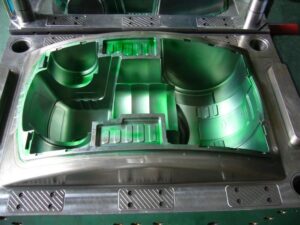
While the effect of the cooling lines on the structure of the shape can be particularly intense in embellishment applications with high dissolve pressures, the potential effect stays noteworthy in many applications since the cyclic stacking and emptying of the soften pressure offers ascend to disappointment because of exhaustion. More terrible, erosion of the metal by the coursing coolant will in general fuel the pressure focuses. Breaks can frame, consume, and spread through the form to the pit and along these lines require fix.

Trim machine administrators from high precision plastic injection mould suppliers ought to have the option to work the injection mold with negligible data. The quantity of outside associations ought to be kept to a base, with ideally two associations (one bay and one outlet) per shape half. Every one of the associations ought to be labeled”in”and”out”to help the administrator abstain from framing a dead cooling circuit. Many disintegrates shading code gracefully lines (blue) and return lines (red), so shape arrangement is encouraged by correspondingly anodizing or giving hued names to the form gulfs and outlets. To evade harm to the cooling system, all outside segments ought to be recessed to maintain a strategic distance from direct contact with tie bars, work tables, or different iterms.

Given that there are numerous goals in the plan of the cooling system, it is improbable that each target will be all the while enhanced. The objective is for the mold architect to arrive at a decent trade off, with the end goal that quick and uniform cooling is accomplished in a savvy way. The accompanying seven stage investigation is given to help the mold plan choices that must be made. A while later, some basic cooling issues and plans are created.

This article is from http://www.chinainjectionmold.com/

Runner Size

The past examination and molds applied to a normally adjusted stretching feed system. Be that as it may, the investigation can likewise be applied to”artificially adjusted” feed system plans for family forms and multi-gated parts. In these applications of high precision plastic injection mould suppliers, distinctive stream rates and weight drops might be wanted for each part of the feed system.

To appropriately adjust the stream rates and soften pressures in a shape with complex Cavity calculations, it is important to guarantee that the polymer dissolve finishes the filling of each part of the form at around a similar time. Accordingly, the initial step of the examination is to ascertain the ideal volumetric stream rate to every hole, or for a multi-gated part, in each bit of the pit. The filling pressure at each entryway is . At that point assessed expecting this stream rate. When the hole pressures are known, at that point the weight drops through each bit of the runner system of high precision molds made in china can be planned with the recently portrayed investigation to yield the ideal depression weight and stream rate.
While this examination approach is as basic as could reasonably be expected, it doesn’t represent disparities in the occupying season of the feed system itself. This mistake is regularly unimportant since the feed system has a little volume contrasted with the shape depressions for cold runner forms and is as of now filled for hot sprinter molds. All things being equal, the absolute occupying time and weight of each part of the feed system and the shape cavities ought to be assessed to guarantee a really adjusted plan; numerous emphases might be expected to accomplish an adequate plan.

The mold designer of china cnc machine for mold making ought to perceive that a really ideal, adjusted form configuration is incredibly hard to accomplish. Since polymer dissolves are non Newtonian and the shear rates shift with sprinter breadth and stream rates, the im balance over the feed system is an element of the material properties and the preparing conditions.

Besides, there is no assurance that a feed system intended to adjust the stream rates during the filling stage will likewise adjust the pac ruler pressures during the posi-illing stage. Thusly, the shape planner ought to endeavor to lessen the measure of adjusting required by the feed system by guaranteeing the consistency of the form hole plans with the understanding that there will be cutoff points to the presentation of static feed systems.

For cold runner form plans, the shape planner should appraise the time needed to set the cool sprinter just as the time needed to harden the depression. The cementing times can be assessed through one – dimensional warmth move investigation as examined by china industrial injection mold suppliers. Table 6.2 gives the cooling time conditions to strips and chamber calculations, where h is the divider thickness of the pit, D is the breadth of a part of the feed system, Teiect is the predefined launch temperature (generally taken as the redirection temperature under burden, or DTUL), Tcoo Oolant is the coolant temperature, and Tmelt is the soften temperature.

During the embellishment cycle, the cooling time will be overwhelmed by whatever segment of the shape requires the longest an ideal opportunity to cool. Consequently, it isn’t important to compute the cooling times for each bit of the feed system and each shape pit thickness. Rather, the form planner can essentially check the cooling time for the thickest shape pit area and the biggest feed system measurement (for the most part the distance across at the base of the sprue). In the event that the cooling season of the feed system enormously surpasses the cooling season of the shape pits, at that point the form architect ought to overhaul the feed system to abstain from expanding the trim process duration.

This article is from http://www.chinainjectionmold.com/.

Moulding Design Parts

Corner Design

For china precision mould manufactory, sharp corners are frequently indicated in item configuration to amplify the inside volume of a segment, to encourage mating between parts, 0r to improve the style. In any case, sharp corners in shaped items ought to be kept away from for some, reasons identified with item execution, form structure, and infusion shaping:

  1. Relative to item execution, sharp corners will bring about a pressure focus that may cause many (and particularly weak) materials to fall flat under burden.

Moreover, a case with sharp corners and tall sides might not have the torsional solidness of an adjusted b0x with shorter sides.

  1. Relative to form making, sharp corners can be extremely hard to create, requiring the utilization of electrical release machining or the utilization of numerous cutting goes with instruments of diminishing size.
  2. Some basic rules for fileting and chamfering corners are given, the filet sweep 0n an outside corner ought to be 150% of the divider thickness. To keep up a similar thickness around the bend, the filet on the inward corner is set to half of the divider thickness. In most present day solids-based CAD frameworks, these filets can be promptly accomplished by fileting the outside edges preceding shelling of the part. These filet suggestions are just rules. Truth be told, significantly bigger filets can be utilized to energize more uniform shape cooling. In all cases, the form architect ought to recommend a filet span that relates to promptly accessible tooling calculation s0 that custom instruments need not be hand crafted.

Chamfers are regularly used to break sharp corners with a solitary inclined surface interfacing the external surfaces, frequently at a 45-degree edge. A shallow chamfer of short of what one-a large portion of the divider thickness is frequently used on outside corners to accommodate satisfactory help while keeping away from potential negative issues identified with liquefy stream and part quality. Like filets, bigger chamfers might be applied preceding shelling to give improved part solidness and warmth move close to the corners.

Surface Finish and Textures

Surface completion and surface are usually indicated by the part fashioner, yet significantly affect the shape plan and cost. Most form making organizations are equipped for giving excellent surface completions, however cleaning can be re-appropriated to bring down cost organizations and nations because of its high work content. Surface finishing requires a more elevated level of aptitude and innovation, with a generally little subset of organizations giving a critical segment of shape finishing surfaces.

Surface completions of high precision plastic making mould china are regularly assessed by guidelines of the Society of the Plastics Industry. These completions run from the D3, which has a sand-shot appearance, to A1, which has a mirror finish.

The expense of formed partsĀ  of precision plastic injection mould factory can increment significantly with more significant levels of surface completion. The explanation is that the use of a given surface completing requires the shape producer to progressively apply all the lower-level surface completing techniques. For instance, to get a SPI C3 finish, the form would initially be treated with coarse and fine dot impacts followed by cleaning with a #320 stone. Therefore, more elevated levels of surface completion cost altogether more than lower levels. Besides, molds with elevated levels of finish can create moldings in which imperfections are profoundly noticeable, along these lines adding cost to the infusion shaping procedure and form support necessities.

As a choice to smooth surface completions, numerous item plans determine a finished completion. One normal explanation is that surfaces might be utilized to bestow the presence of wood, cowhide, or different materials. Therefore, surfaces may build the apparent estimation of the plastic trim by the end-client. Another explanation is that finished surfaces give a lopsided profundity which might be utilized to shroud deformities, for example, sew lines, imperfections, or different blemishes. Likewise, surfaces might be utilized to improve the capacity of the item, for example, by giving a surface that is anything but difficult to hold or concealing scratches during end-use.

Finishing adds essentially to the expense of the shape. To apply a surface, shape surfaces should initially be done normally to SPI class B for shallow surfaces (in which the surface profundity is on the request for a couple of microns) or class C for unpleasant surfaces. Something else, the hidden helpless surface completion might be noticeable after the applied surface. After surface completing, the surface is pervaded to the shape surfaces utilizing concoction drawing or laser machining forms. Since committed handling gear is required, the shape improvement process must give sufficient time and cash to the form finishing.

This article is from http://www.chinainjectionmold.com/.