Turning Center

Folding centers are generally easy to fuse into shape plans when utilizing a bought gathering, and can be utilized for the framing of strings, dimples, windows, and other interior highlights. Be that as it may, one issue with folding centers is the development of witness lines on the inside of the shaped part where the center portions interface. Depending 0n the application necessities, these observer lines may disallow the utilization of the folding centers. In that capacity, various shape plans have been created with turning centers for the arrangement and demolding of inner strings. One plan is shown in oem/odm industrial injection moulding design factory for a 64 depression form for the creation of strung covers [13]. The shape configuration incorporates cavities 16 that are framed by coordinating arrangements of hole embeds 10 and center supplements 15. The rear of each center incorporates a vital help 17, which is mounted upon a shaft 18 that reaches out from a coarsely strung helix 19. The helix is pivotally situated between the back brace plate 21 and the help plate 23, and radially upheld by course 20 and 26.

1

Devotee pins 30 have been fitted to the incited plate 29 that connect with the strings of the helix 19. Since these pins can’t pivot, the activation of the plate 29 will cause the revolution of the helix 19, and the resulting turn of the strung centers 15. Concerning plan, a coarsely strung helix is fundamental since the force and wear will increment considerably as the pitch diminishes. All things considered, the necessary length of the helix is identified with the erosion between the helix and the supporter, just as the quantity of pivots in the embellishment application.

Another shape plan for turning centers is appeared in the arrangement perspective on mould manufacturers china. In this form plan, a focal sun gear 84 at the same time activates different planetary pinion wheels 86, which thus drive shafts 88. The center supplements are not appeared in plastic molding services china, however are keyed to the drive shafts through spaces 66. There are numerous potential plans to turn the sub stuff 84. In this plan, a pinion 42 is connected to a shaft 74 which closes at a slope gear 76. This slope gear 76 lattices with another slant gear 78 that is bolted to the focal sun gear 84. In activity, the form opening stroke causes

■the rack 44 to draw in the pinion 42,

■the pinion 42 to pivot the shaft 74,

■ the shaft 74 to pivot the incline gear 76,

■the slope gear 76 to pivot the incline gear 78,

■the slant gear 78 to turn the sun gear 84,

■ the sun stuff to pivot the planetary cog wheels 86,

■ the planetary cog wheels 86 to turn the shaft 88, and

■the shaft 88 to pivot the centers keyed to opening 66.

With either plan procedure, the high-precision molds made in china ought to guarantee that the part calculation is intended to forestall the turn of the shaped part with the pivoting center. Now and again, the sprinter and door may give adequate solidarity to forestall the formed part’s revolution. In different cases, nonetheless, this methodology is insufficient since the discharge powers will in general shift with the material properties, preparing conditions, and surface completion as examined before in china mould design services. Therefore, the mold configuration may utilize some little undermines or other nonasymmetric highlights to forestall the part revolution.

This article is from http://www.chinainjectionmold.com/
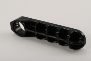
Ejection Push Part

When the launch powers on the embellishment have been assessed, the following stage is to decide the total”push territory” of the ejectors onto the shaped part. In particular, there is a base push territory that is needed to maintain a strategic distance from inordinate compressive weight on the discharge system segments just as unnecessary shear weight on the plastic moldings. These two marvels are represented by china mould design services for a solitary pin shooting a bit of the PC bezel.

At the point when the pin is activated with the discharge framework, a response power, Fpin, will create between the pin and the shaped part before the part is shot out. The greatness of this power is identified with the all out discharge power needed to launch the part just as the number, area, and math of the ejectors. The compressive stres on the pin, Opin, is the power on the pin isolated by the region of the pin, or: σpin=Fpin/Aacompession

To stay away from exhaustion or potentially clasping of the launch framework segments, compressive feelings of anxiety must be kept up under a basic edge. This basic pressure, 0 fatigue_ limit is needy upon the material and treatment of the ejectors. Most ejector pins and sleeves are made of solidified materials, with exhaustion limit weights on the request for 800 MPa. A traditionalist shape plan, notwithstanding, may expect a lower weariness limit pressure of 450 MPa for P20. In one or the other case, the all out push territory, all things considered, Aejectors, to keep away from over the top compressive anxieties must meet the necessity.

The necessary push territory to evade abundance compressive anxieties in the discharge framework is exceptionally little in most trim applications invigorated the moderately high of steel. High-precision molds made in china know that the compressive quality of the pins is accordingly not compelling the plan.

Be that as it may, the ejector framework should likewise have enough push zone to try not to create exorbitant shear stresses in the shaped parts upon discharge. For oem/odm industrial injection moulding design factory, the shear pressure applied on the formed part is the power on the pin separated by the territory of the shaped part straightforwardly over the boundary of the pin, or: :

where Qnin is the border of the pin. In the event that the shear pressure in the shaped part is too high, at that point the part can for all time mutilate close to the pin (an impact known as”push pin”), forever twist, or even crack. To dodge these deformities, the form should be planned with the end goal that the edge around all the ejectors gives a shear pressure short of what one-a large portion of the yield pressure of the material, Oplastic veld. This prerequisite prompts the accompanying relationship for the all out border of the ejector framework.

The examination and models show that for most trim applications, the plan of the ejector framework is driven more by the yield stresses applied on the plastic embellishment as opposed to by the compressive weights on the pin. Notwithstanding, compressive pressure can cause locking in long, thin individuals, for example, ejector pins. Consequently, further investigation of the compressive anxieties is significant, and will be accordingly used to dodge pin clasping. This article is from http://www.chinainjectionmold.com

Molding Principles

oem/odm medical mold design factory suggests that interminably high warmth move rates can be accomplished by moving to higher conductivity materials and utilizing many cooling lines extremely near the surface. In any case, there is a point where further interest in the cooling system receives no benefits. The explanation from the high precision molds made in china is that the warmth move rate becomes restricted not by the warmth conduction through the shape, yet rather by the warmth conduction through the plastic just as the warmth convection to the form coolant. Thus, molds made out of exceptionally conductive materials may have a huge decrease in the process duration by improving warmth conduction through the form, however nothing close to the eight-overlap improvement that may be foreseen from these material’s high warm conductivity esteems.

The way to planning a financially savvy form is to realize where to contribute. Profoundly conductive materials are amazingly powerful in certain applications and are typically simpler to machine, yet are not generally best. Thus, cooling line formats can go from the easy to the complex. Complex cooling line plans regularly require generous macintosh hining, stopping, fixing, fitting, and upkeep. It is significant for the form creator to know when the additional expense of an unpredictable cooling framework configuration is defended.

The liquefy will apply huge weights on the surfaces of the shape cavities. These powers make an interpretation of straightforwardly into noteworthy worries inside the form plates and embeds. The form’s auxiliary respectability is debilitated by each cooling line, every one of which requires the expulsion of supporting mold material and furthermore gives a pressure fixation.

While the effect of the cooling lines on the structure of the shape can be particularly intense in embellishment applications with high dissolve pressures, the potential effect stays noteworthy in many applications since the cyclic stacking and emptying of the soften pressure offers ascend to disappointment because of exhaustion. More terrible, erosion of the metal by the coursing coolant will in general fuel the pressure focuses. Breaks can frame, consume, and spread through the form to the pit and along these lines require fix.

Trim machine administrators from high precision plastic injection mould suppliers ought to have the option to work the injection mold with negligible data. The quantity of outside associations ought to be kept to a base, with ideally two associations (one bay and one outlet) per shape half. Every one of the associations ought to be labeled”in”and”out”to help the administrator abstain from framing a dead cooling circuit. Many disintegrates shading code gracefully lines (blue) and return lines (red), so shape arrangement is encouraged by correspondingly anodizing or giving hued names to the form gulfs and outlets. To evade harm to the cooling system, all outside segments ought to be recessed to maintain a strategic distance from direct contact with tie bars, work tables, or different iterms.

Given that there are numerous goals in the plan of the cooling system, it is improbable that each target will be all the while enhanced. The objective is for the mold architect to arrive at a decent trade off, with the end goal that quick and uniform cooling is accomplished in a savvy way. The accompanying seven stage investigation is given to help the mold plan choices that must be made. A while later, some basic cooling issues and plans are created.

This article is from http://www.chinainjectionmold.com/
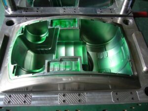
Runner Size

The past examination and molds applied to a normally adjusted stretching feed system. Be that as it may, the investigation can likewise be applied to”artificially adjusted” feed system plans for family forms and multi-gated parts. In these applications of high precision plastic injection mould suppliers, distinctive stream rates and weight drops might be wanted for each part of the feed system.

To appropriately adjust the stream rates and soften pressures in a shape with complex Cavity calculations, it is important to guarantee that the polymer dissolve finishes the filling of each part of the form at around a similar time. Accordingly, the initial step of the examination is to ascertain the ideal volumetric stream rate to every hole, or for a multi-gated part, in each bit of the pit. The filling pressure at each entryway is . At that point assessed expecting this stream rate. When the hole pressures are known, at that point the weight drops through each bit of the runner system of high precision molds made in china can be planned with the recently portrayed investigation to yield the ideal depression weight and stream rate.
While this examination approach is as basic as could reasonably be expected, it doesn’t represent disparities in the occupying season of the feed system itself. This mistake is regularly unimportant since the feed system has a little volume contrasted with the shape depressions for cold runner forms and is as of now filled for hot sprinter molds. All things being equal, the absolute occupying time and weight of each part of the feed system and the shape cavities ought to be assessed to guarantee a really adjusted plan; numerous emphases might be expected to accomplish an adequate plan.

The mold designer of china cnc machine for mold making ought to perceive that a really ideal, adjusted form configuration is incredibly hard to accomplish. Since polymer dissolves are non Newtonian and the shear rates shift with sprinter breadth and stream rates, the im balance over the feed system is an element of the material properties and the preparing conditions.

Besides, there is no assurance that a feed system intended to adjust the stream rates during the filling stage will likewise adjust the pac ruler pressures during the posi-illing stage. Thusly, the shape planner ought to endeavor to lessen the measure of adjusting required by the feed system by guaranteeing the consistency of the form hole plans with the understanding that there will be cutoff points to the presentation of static feed systems.

For cold runner form plans, the shape planner should appraise the time needed to set the cool sprinter just as the time needed to harden the depression. The cementing times can be assessed through one – dimensional warmth move investigation as examined by china industrial injection mold suppliers. Table 6.2 gives the cooling time conditions to strips and chamber calculations, where h is the divider thickness of the pit, D is the breadth of a part of the feed system, Teiect is the predefined launch temperature (generally taken as the redirection temperature under burden, or DTUL), Tcoo Oolant is the coolant temperature, and Tmelt is the soften temperature.

During the embellishment cycle, the cooling time will be overwhelmed by whatever segment of the shape requires the longest an ideal opportunity to cool. Consequently, it isn’t important to compute the cooling times for each bit of the feed system and each shape pit thickness. Rather, the form planner can essentially check the cooling time for the thickest shape pit area and the biggest feed system measurement (for the most part the distance across at the base of the sprue). In the event that the cooling season of the feed system enormously surpasses the cooling season of the shape pits, at that point the form architect ought to overhaul the feed system to abstain from expanding the trim process duration.

This article is from http://www.chinainjectionmold.com/.