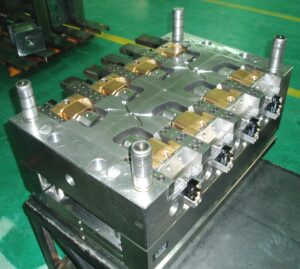
To give as protected and proficient a shape as could reasonably be expected, the form creator ought to indicate the utilization of limit changes to affirm that the moving center is in its forward or withdrawn position, These position signs can be utilized by the embellishment machine to guarantee that the moving centers are appropriately situated to not harm the formed parts or the infusion form during mold opening or part discharge. Moreover, the form architect ought to endeavor to plan the moving center with the end goal that the shape opening or part discharge doesn’t harm the shape if the moving center is inappropriately situated. Consider, for instance, the plan appeared in china high precision mold supplier. On the off chance that the shape is opened and the part shot out with the pushing center in its ahead position, all things considered, the plastic part will be sheared off at the essential rib by the incitation of the close by ejector sleeve and ejector edge. Clearly, this occasion is undesired and ought not happen for an appropriately set embellishment measure. Notwithstanding, such occasions do happen and decays enormously like a powerful form plan that can withstand discontinuous maltreatment without adjusting the ejector pins, cutting edges, sleeves, or moving centers.

Center pulls are very regular since they permit moving supplements to be activated in various ways, strokes, and times. In any case, center pulls require actuators, auxilliary control, and huge space. Therefore, form originators regularly like to utilize sliding centers that are incited by slanted point pins.
One such shape configuration is appeared in oem/odm industrial injection mold design factory. In this plan, a bronze gib is situated in the B plate to give a greased up sliding surface to the moving supplement. The center addition is furnished with a slanted can surface that mates with the point pin, As the form opens and shuts, the point pin draws in the sliding center, making the center move in and out. A retainer plate made sure about to the B plate keeps the sliding center from dropping out of the gib.
The point by point configuration is appeared in china custom mold components and warrants further conversation. The point pin is situated using a point pin embed, which has a level surface to arrange the point pin toward the sliding activity. While there are numerous approaches to plan a slide for side activity, the point pin embed is held between the center addition and a heel block by attachment head cap fastens this plan. On the moving side of the shape, the bronze gib is situated with dowels and affixed with cap sinks to a pocket cut the B plate and center supplement. The gib gives a keyway into which directs the sliding center. The sliding center itself is fundamentally the same as that recently appeared in oem/odm industrial injection moulding factory.
In activity, the clasping of the shape makes two powers be forced on the sliding center. To start with, the calculated surface on the heel block contacts the calculated surface on the slide to constrain the slide along the side against the center addition; this parallel power withstands the dissolve pressure and forestalls blazing of the ribs, supervisors, and window. Second, the pit embed contacts the top surface of the slide, which gives a descending clasping power to forestall redirection and glimmering around the splitting line of the trim. It should be noticed that the point pin doesn’t give the sidelong power and isn’t exposed to huge pressure in this plan. All around planned clearances, resiliences, and fits are pivotal to the capacity and life span of the sliding center.
This article is from http://www.chinainjectionmold.com
 Many embellishment application necessities are best satisfied by custom feed systems that don’t consent to any of the past feed system formats. For instance, numerous multigated parts require the feed system to convey soften to various areas over the mold pit. In such embellishment applications, there is no motivation to hold fast to either extended or outspread or even normally adjusted designs. Without a doubt, the mold architect ought to intentionally pick a feed system format and determine measurements that convey the ideal measure of polymer dissolve at the ideal liquefy weights to various bits of the mold cavities.