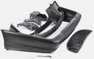
A shape cutting cycle uses the layered assembling procedure for quick prototyping in chinese laser cutting prototype manufacturers.
In any case, it varies from other RP frameworks in that, instead of working up a section by adding materials to a stack through a shaping cycle, layers of sheet materials, for example, paper, plastics, or composites are appended to a stack, and a laser removes the unused parts.
A delegate shape cutting cycle is Laminated Object Manufacturing (LOM) created by Helisys Inc. in 1985. The cycle starts with a PC cutting a 3D strong model of the part into 2D cross-segments. Info information is in the STL document design. The thickness of the PC produced cross-segment compares to the thickness of the sheet material. The sheets can be 0.001-0.005 in. thick and a winding and a loosening up roll give a strip of the material. Figure 6.73 shows the schematics of a form cutting cycle. It is fit for creating parts that can be machined or sanded to give great surface completion, however since the parts are produced using paper, they should be fixed from dampness.
Profiles of item cross-segments are cut from paper utilizing a laser as appeared in precision cnc machining solutions factory. The paper is loosened up from a feed roll (A) onto the stack and clung to the past layer utilizing a warmed roller (B). The roller liquefies a plastic covering on the base side of the paper to make the connection between layers. The profiles are followed by an optics framework that is mounted to a X-Y stage (C). The cycle produces extensive smoke. Either a fireplace or a charcoal filtration framework (E) is required and the manufacture chamber (F) must be fixed.

After the cutting of the mathematical highlights of a layer is finished, the overabundance paper is removed to isolate the layer from the web. The additional paper of the web is twisted on a take-up move (D). The strategy is self-supporting for shades and undermines. Territories of cross-segments that are to be taken out in the last article are vigorously crosshatched with the laser to encourage evacuation. It very well may be tedious to eliminate additional material for some math.
In a shape cutting cycle, the material is situated onto the structure stage and a warmed roller moves over the outside of the material, holding it to the stack as appeared in Figure 6.74a. A X-Y situating table with mirrors and optics reflects and centers the CO2 laser bar, which cuts a profile of the part as appeared in plastic or metal machining parts china. The region of material encompassing the part profile is sliced in a crosshatch example to encourage its expulsion later by china precision machining services manufacturers. The abundance material left on the structure block goes about as a help structure for the following layer. Changes in the laser force and slicing speed empower it to slice through just each layer in turn. The stage brings down to oblige another layer of sheet material as appeared in fashion sheet metal rapid prototyping, in which the moves advance, and the warm roller bonds to the stack as appeared in Figure 6.74f. Another layer of material is then clung to the head of the recently cut layer. The laser cuts another cross-area as in Figure 6.74g and this cycle proceeds until the part is finished as appeared in Figure 6.74h.
This article is from http://www.chinainjectionmold.com/