Molding Pressure Control

The pressure strain conduct of two normal shape metals, P20 and aluminum QC7, are plotted in oem/odm industrial mold factory. P20 has a lot higher modulus than QC7, implying that it will display less strain and misshapening given an applied burden or stress. The yield pressure is where the material withdraws from its straight conduct. The yield pressure is likewise the pressure at which the material plastically disfigures, implying that the segments with a higher pressure won’t re-visitation of their unique shape after the heap is taken out. When the material surpasses the yield pressure, it can keep on conveying load up to a definitive pressure, after which it flops totally.

All shape plans should be designed to work at stresses lower than the yield pressure. Regarding determining a wellbeing component to relate the yield pressure as far as possible pressure, there are two basic methodologies. One methodology is to just set the cutoff stress equivalent to the yield pressure, however then accept a most dire outcome imaginable concerning the heap condition. For instance, a form fashioner working with P20 could accept a cutoff stress equivalent to the yield pressure of 830 MPa. To guarantee the form doesn’t yield under burden, the shape fashioner should then perform examination accepting the most noteworthy liquefy pressures that the form could actually be required to see, maybe 200 MPa.
Another methodology for precision molds made in china is to set the breaking point pressure equivalent to the yield pressure partitioned by a factor of security: σlimmit=σyield/f, where fis the factor of wellbeing, whose worth is identified with the degree of vulnerability and the expense of a possible disappointment, Typical qualities range from 1.5 for non basic form segments to 6.0 for raise rings.When a factor of security is utilized, the shape fashioner ought to apply the normal dissolve pressure for the shape, maybe 100 MPa.

To try not to over-plan the mold, the mold designer of oem/odm industrial mold design factory ought not mutually apply a factor of security with the most dire outcome imaginable. While the form creator may expect that a plan dependent on the yield pressure with a moderate factor of security would be hearty, this methodology may bring about molds that fizzle after countless embellishment cycles. The explanation is that the contin ued cycling of bracing burdens and liquefy pressure in the shape pit causes cyclic anxieties as appeared in high precision plastic making mould suppliers china. Each pressure cycle permits little breaks in the form to open and close, causing a couple of more gems at the break tip to fall flat. Throughout the span of thousands of embellishment cycles, these breaks will develop and engender through the form like a wedge driven by a mallet. When the break arrives at a basic size, the pressure focuses around the break will make the shape flop in any event, when the form was appropriately planned with a cutoff stress determined well underneath the yield pressure. This disappointment mode is by and large alluded to as weakness. This article is from http://www.chinainjectionmold.com/
Two-Plate Molds

The formats of the various kinds of feed systems from high-precision mould manufactory and their going with segments are examined in more noteworthy detail.

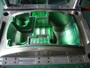
The two-plate mold is so named in light of the fact that it comprises of two amassed areas that sandwich the dissolve; every 50% of the form can comprise of at least one mold plates. A segment of an isometric mold is given in Fig. 6.4, in which the concealing speaks to the movement of the polymer liquefy. During the embellishment cycle, the spout of the trim machine mates with the span of the sprue bushing. The polymer dissolve first streams down the sprue bushing, accordingly crossing the thickness of the top brace plate and A plate. The material at that point streams over the splitting plane through sprinters and entryways into at least one mold pits.

After the polymer is completely infused and set, the mold is opened at the splitting plane, which is situated between the An and the B plates. Regularly, the A portion of the mold stays fixed while the B half of the form is pulled away with the moldings and sprinter framework staying on the center. To encourage launch, a converse mold is normally given on a take out pin beneath the sprue to guarantee that the sprue and appended sprinter stays with the B half. After the form has opened adequately to eliminate the moldings, the ejector plate is pushed forward by the embellishment machine. The sprue take out pin pushes on the sprue, breaking the little undercut and shooting the sprue from the B side of the mold. Extra ejector pins and take out pins can be put down the length of long sprinters to encourage launch of the feed framework.

In the plan of the feed system of oem/odm automotives injection molding factory, the length of the sprue is controlled by the joined thicknesses of the top clip plate and the A plate. The lengths of the sprinters are controlled by the situation of the depressions and the format of the related sprinters. Given this format, the mold creator needs to determine the widths of the feed framework. When all is said in done, the distances across of the upstream sprinters are bigger than the measurements of the downstream sprinters, since the progression of the polymer soften branches at sprinter intersections and there will be a lesser stream rate through every one of the downstream sprinters.

While a two-hole two-plate mold is utilized to show form plan ideas, the gave examination can be applied to more perplexing feed framework formats. For instance, china injection molded parts factory gives a feed system plan to an eight-cavity family form, including two essential sprinters, four optional sprinters, and eight tertiary sprinters. On the off chance that the stream rate through the sprue was 100 cc/s, at that point the stream rate through every one of the essential, optional, and tertiary sprinters would separately be 50 cc/s, 25 cc/s, and 12.5 cc/s. On the off chance that the stream obstruction in the depressions differed generously, nonetheless, at that point the stream rate in the tertiary sprinters could fluctuate considerably during the form filling stage.

Likewise with the feed system configuration appeared in oem/odm industrial mold factory, the distance across of each downstream sprinter is littler than the upstream sprinter appeared in Fig. 6.6. There is one prominent special case: the width of the trim machine’s spout opening is ordinarily littler than the distance across of the sprue delta. The littler opening in the machine spout gives a highlight division between the molded sprue and the cemented plug in the spout of the trim machine. In the event that the spout opening were bigger than the sprue bay, at that point a solidified part of plastic in the spout behind the sprue bushing could make the sprue adhere to the A portion of the mold. At the point when such staying occurs oftentimes, the decay may decide to perform a”sprue break” by withdrawing the infusion unit of the embellishment machine from the machine spout preceding mold opening and part launch. This activity is bothersome since it adds multifaceted nature and fluctuation to the embellishment cycle, so the form planner ought to check as well as suggest the spout hole measurement properly.

This article is from http://www.chinainjectionmold.com/